| S/N | Avanti VSAT System | RESULT/REMARK |
|---|---|---|
| 1 | Check antenna has no dents or visible damage around its edges and/or on the main part of the dish itself |
Ok |
| 2 | Check antenna mounting pole and bracket are plumb by using a spirit level | Ok |
| 3 | Check antenna mounting pole and bracket are secure and will not move with any wind or other external factor |
Ok |
| 4 | Check all screws and bolts on antenna and bracket are tight | Ok |
| 5 | Check the Line of Sight view is clear of any external obstructions such as buildings, trees, tower masts or wire fencing. |
Ok |
| 6 | Check to Confirm that there is no potential future obstruction to Line of Sight such as a young tree that may obstruct the Line of Sight by the next season. |
Nok |
| 7 | Check iLNB transceiver is set to correct polarization (view settings on AMA or OSS). a. Do not adjust the polarization unless you are an authorized installer as you may be required to repoint the antenna. |
Ok |
| 8 | b. If the polarization is set incorrectly, the site will experience either no signal or a very |
Ok |
| 9 | Check to ensure Cable and connectors are a major point of failure in VSAT installations. Ensure cable connectors are correctly terminated with a compression tool and not of the screw type |
Ok |
| 10 | Check to ensure cable route is neatly laid out from antenna to modem placement |
Ok |
| 11 | Check to ensure cabling has no kinks or extreme bends | Ok |
| 12 | Check to ensure no cable or zip ties are used around any electrical cable | Ok |
| 13 | Check that the cabling has a service loop by the antenna. a. This is industry best practice in event of any return site visits where cable ends may need to be cut and reconnected. Service loops permit existing cabling to be used without the need for a full replacement. |
Ok |
| 14 | Check to ensure any conduit or cable entry point from antenna to outdoor cabinet to is properly sealed so as to be dust and waterproof. |
Ok |
| 15 | Check that the modem is powered up with lights on | Ok |
| 16 | Check to ensure the port marked RX/TX is used for the single coaxial cable on the Avanti modem |
Ok |
| 17 | Ensure modem is correctly placed in its optimal position
a. Vertical for Newtec 2210 modem b. Horizontal for Newtec 2510 and 3310 modem b. Horizontal for Newtec 2510 and 3310 modem |
Vertical |
| 18 | Check to ensure VSAT equipment if properly grounded | Ok |
| 19 | If modem is used in outdoor power cabinet:
a. Check to ensure modem is placed as close to bottom of cabinet as possible b. Check to ensure modem is place near an air vent or separate fan for heat dissipation within closed environment |
Ok |
| 20 | In a rural mobile tower deployment: a. Check to ensure antenna is not partially obstructed by solar panels or panel mounts. |
Ok |
| 21 | b. Check to ensure outdoor power cabinet is located below solar panels or other
covering for added sun protection |
Ok |
| S/N | PW/HUAWEI Radio Equipment | RESULT/REMARK |
|---|---|---|
| 1 | Radio Equipment OEM | PW |
| 2 | Check visual Inspection for any product physical damage | Ok |
| 3 | Check antenna and Radio/BTS installed at correct Height as per Site Design | Ok |
| 4 | Check antenna mounted securely on pole mount as per installation guidelines | Ok |
| 5 | Check antenna mounted with no overlap between Antenna and pole mount | Ok |
| 6 | Check Radio/BTS mounted securely on pole mount as per installation guidelines | Ok |
| 7 | Check horizontal Separation on Antenna greater than 1m | Ok |
| 8 | Check to confirm that DC and ground cables are fixed tightly and laid neatly | Ok |
| 9 | Check the connection of RF Cables (Jumpers) from Radio/BTS to Antenna as per installation guidelines |
Ok |
| 10 | Check to confirm that the RF Cables (Jumpers) have been tightened as per Installation guidelines |
Ok |
| 11 | Check the connection of the DC Power Cable to the DC power Plug | Ok |
| 12 | Check the connection of the DC Power Cable to BTS as per Installation Guidelines |
Ok |
| 13 | Check the connection of the GPS Antenna to Radio/BTS as per Installation Guidelines |
Ok |
| 14 | Check to ensure all Cables are labelled with weather-proof label and readable text |
Ok |
| 15 | Check to ensure that the GPS and RF connections on Radio/BTS and Antenna are waterproof |
Ok |
| 16 | Check that the termination of the DC power cable to Power System/Circuit Breaker is done properly |
Ok |
| 17 | Check that the ethernet Cat 6 cable is terminated properly to the Transmission System |
Ok |
| 18 | Check to confirm that all cables are secured with Cable outdoor ties | Ok |
| 19 | Check to ensure that unused connectors on Radio/BTS are covered | Ok |
| 20 | Inspect Site and remove any loose tools, materials, and parts | Ok |
| 21 | Verify that all the exterior mounting hardware and cable connections are secure | Ok |
| 22 | Check the overall appearance of the Radio/BTS, ensuring there is nothing unbalanced, unsecured, or out of alignment and that there is no unintended mechanical alteration of BTS, mounting brackets, or support structure |
Ok |
| 23 | Check to confirm that BTS/Antenna is mounted correctly on the tower/monopole height as designed | Ok |
| 24 | Check to confirm there are no physical dent on the rf cable | Ok |
| 25 | Check to ensure site is free of installation debris | Ok |
| 26 | Check ensure Antenna bracket is firmly tightened | Ok |
| 27 | Check to confirm if all Radio/BTS operational lights are on |
| S/N | CBT Power System | RESULT/REMARK |
|---|---|---|
| 1 | Power System OEM | CBT |
| 2 | Check to confirm that no bare conductor is left untapped during the terminations, to avoid short circuit and electric shock |
Ok |
| 3 | Check to ensure that the security light and motion camera sensor are installed properly | N/A |
| 4 | Check and measure voltage of the all inputs and confirm they are powered | |
| 5 | Check that that the earthing system is terminated to the earthing system in the ground. | Ok |
| 6 | Check and confirm that the remote monitoring system is fully functional | Ok |
| 7 | Check to ensure that there is no blockage to sun access, and that the whole mounting structure shall be tilted and have an angle of between 0 and 42 degrees to have maximum sunlight exposure |
Ok |
| 8 | Check to confirm Fan Unit Installation- Inlet/Outlet Orientation is according to CBT recommendation in the user guide. |
Ok |
| 9 | Check to ensure wire Tray Installation was done correctly | Ok |
| 10 | Check to ensure Batteries are connected to their respective controllers (Battery 1,2,3 to Controller 1,2 ,3 ) |
Ok |
| 11 | Check to confirm Gateway installation is within 2" space away from the side of the cabinet |
Ok |
| 12 | Check to confirm that Direct Attach Antenna is attachment to the Gateway | Ok |
| 13 | Check to confirm the orientation of the Direct Attach Antenna is done accordingly | Ok |
| 14 | Check Solar Harness 2C-12AWG 11m connection to ensure it is terminated properly | Ok |
| 15 | Check Solar Harness 2C-12AWG 10m to ensure it is terminated properly | Ok |
| 16 | Check Solar Panel Ground Cable to ensure it is terminated properly | Ok |
| 17 | Check connection of Strain Reliefs for Solar Cables to ensure it’s terminated properly | Ok |
| 18 | Check to confirm that Harnesses are routed through the wire trays in the cabinet | Ok |
| 19 | Check the termination of positive and negative Solar Cable Adaptor Cables | Ok |
| 20 | Check to ensure there is slack for strain relief and solar cables | Ok |
| 21 | Check to confirm that VSAT cables are routed properly and attached to the output connectors connected to the 24V DC/DC Converter. |
Ok |
| 22 | Check to ensure PV mounts are mounted firmly, with tightened bolts at the base and on the solar panels, according to GICL specification |
Ok |
| 23 | Check to conform Installation of 105 Ah Battery is done properly | Ok |
| 24 | Check to confirm that Installation of Cabinet to Battery Bond is done properly | Ok |
| 25 | Check to conform that Installation of Custom Temperature Probe are done properly | Ok |
| 26 | Check to confirm that Controller 1’s temperature probe is connected to Battery 1 temperature probe | Ok |
| 27 | Check to confirm that Controller 2’s temperature probe is connected to Battery 2 temperature probe | Ok |
| 28 | Check to confirm that Controller 3’s temperature probe is connected to Battery 3 temperature probe | Ok |
| 29 | Check to confirm connection of 25A Fuse | Ok |
| 30 | Check to confirm that LED indicators functioning properly | Ok |
| 31 | Check to confirm proper Installation of 12” Cable Spiral Bundle Wrap | Ok |
| 32 | Check to conform proper Installation of ½” Hole Caps | Ok |
| 33 | Check physical location of the batteries, controllers and loads inside the cabinet | Ok |
| 34 | Check controller label & status lights is as clear as possible. | Ok |
| 35 | Check 48v DC/DC converter label & status lights is visible | Ok |
| 36 | Check CUI 24v DC/DC converter label and status light is visible | Ok |
SECTION 2: QUALITY AUDIT REPORT TEMPLATE
| CBT Power System | RESULT/REMARK |
|---|---|
| New IHS Site ID | Basara Village | MTN Site ID | Site Coordinates | Latitude: 11.0751046, Longitude: 8.8034139 |
| Site Address | Basara Bauch Ningi LGA |
| State | Bauchi |
| Task Accomplished by | Yasir Adoji |
| Date of Acceptance | 17-10-2021 |
| Date of Completion | 17-10-2021 |
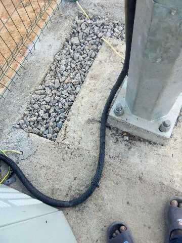
PICTURES
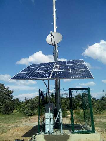 Front veiw | 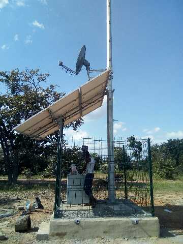 Side veiw | 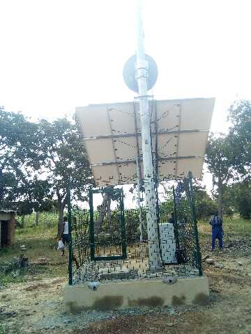 Back veiw |
SECTION 2.1 Power System1. Power System |
||
 Radio Earthing | 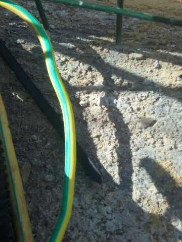 Tower Earthing | 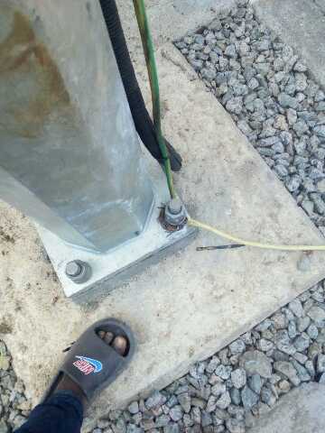 Power Earthing |
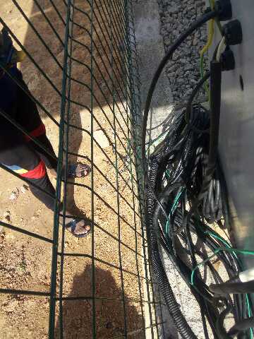
 VSAT Earthing | 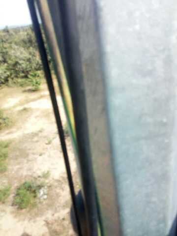 ODU cabling |
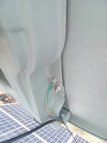
 Gateway |
2. Key Power Components |
||
 DC-DC CONVERTER | 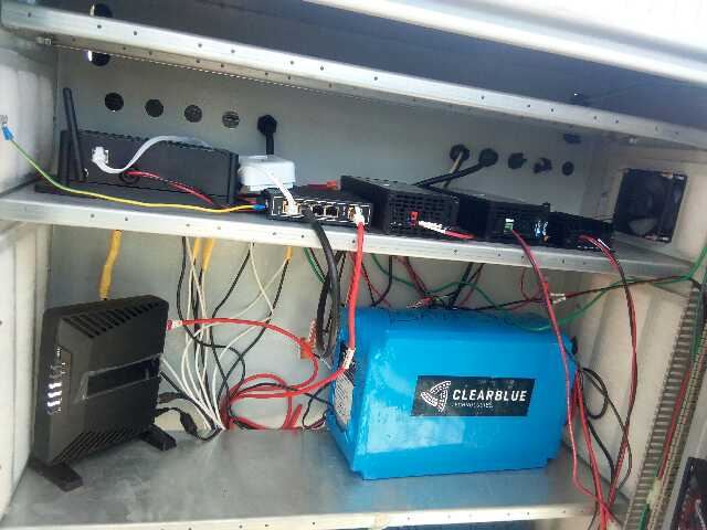 CONTROLER 1 & 2 | 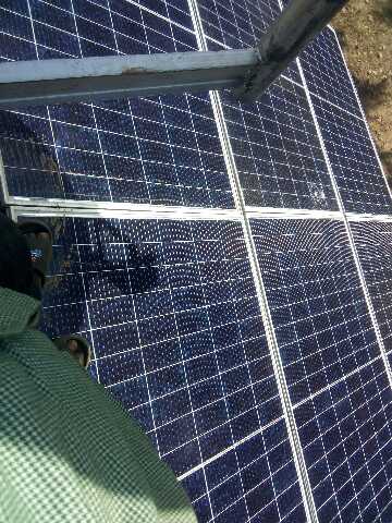 CONTROLLER 3 |
SECTION 2.2 CWS/Antenna System1. RRU/RRP Omni Antenna installation |
||
 Weather Proof | 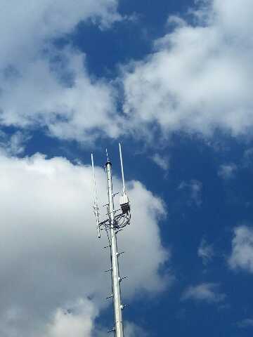 BTS Radio |
|
 Omni Antenna | 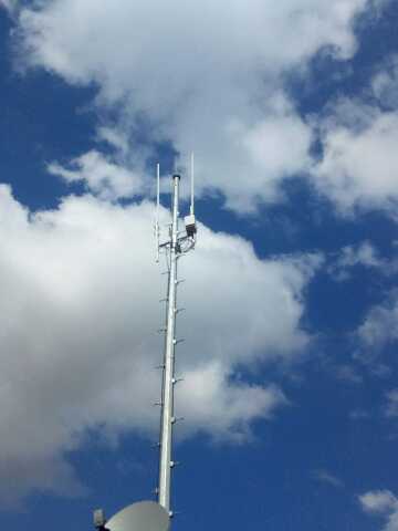 CONTROLLER 4 & 5 |
|
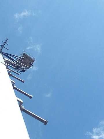
SECTION 2.3 VSAT System |
||
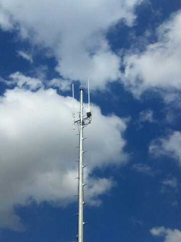
| VSAT Antenna on tower | 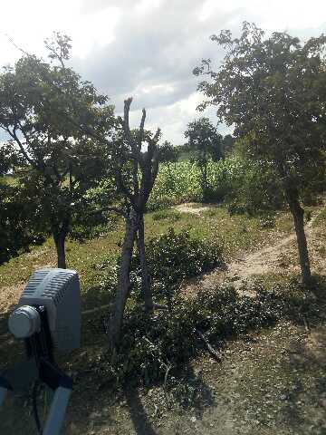 iLNB Transiver /Line of sight |
|
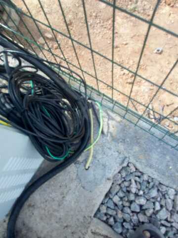
 Cable Termination | 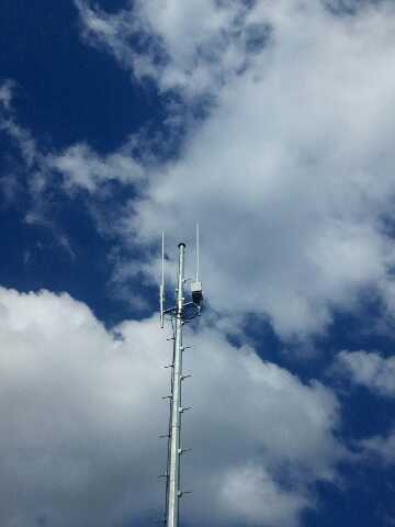 Tower View |
QUALITY AUDIT SIGN OFF
| QA Company Name: | INTROSPECT |
| Name of Quality Auditor | Mustapha Adebiyi |
| Date of Successful NQA Acceptance and Ops Handover | 
26/06/2024 |
| Phone Number | 09024662530 |
| Designaton |